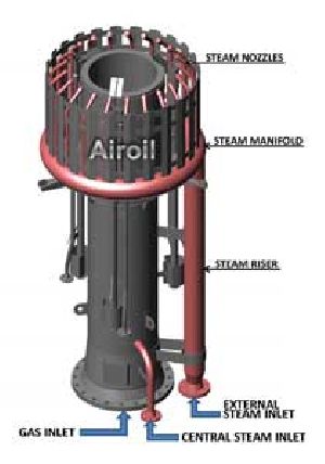
STEAM ASSISTED FLARES
The FUS Series flare tips are the most efficient flare tips utilizing external steam nozzles in addition to central steam nozzles and are suitable for sites where a general low noise flare tip is required. The FUS Series tips are based on externally mixing steam and air with the gas at the point of exit, utilizing steam injection nozzles. A ring of FUS nozzles is located at the top leading edge of the flare tip, inside the wind shield. The steam is discharged from the FUS nozzles entraining large quantities of air into the heart of the gas steam. The gas/air/steam mixture is swirled to entrain large volumes of secondary air resulting in stable combustion condition. This prevents smoke formation from thermal cracking. The "FUS" nozzles produce very low noise compared with conventional external steam nozzle design. The swirling non-converging action of the steam from the "FUS" gives maximum air entrainment and shapes the flame to avoid overheating of the tip. This also helps in preventing flame-lick under low gas flow and high wind condition. "FUS" nozzles are self cleaning by virtue of the steam flow carrying foreign matter through the centre orifice. DESIGN ADVANTAGES Efficient steam injection into flame envelope. Steam economy. Stable construction. Good flame retention. Burn-back minimized. Energy efficient & reliable pilots Continuous Pilot monitoring by means of thermocouple mounted inside the pilot as standard. Optional UV/IR detection available. Wind shield supplied as standard. FLAME STABILITY The FUS series is supplied as standard with a slatted windshield to prevent flamelick and to help cool the top of the flare tip closest to the flame envelop. In order to prevent flame lift off from the tip, the FUS series has unique flame retention lugs positioned at the tip exit of the flare tip. REFRACTORY SYSTEM The unique refractory lining system is secured to tip by heat resistant steel bull horn sprags. Many thousands of fine stainless steel needles are mixed thoroughly with the refractory to reinforce the material evenly over its full depth without producing expansion/contraction shear planes. This refractory installation procedure has been developed and proven over many years to give the longest possible operating life, even in the most arduous conditions.
...more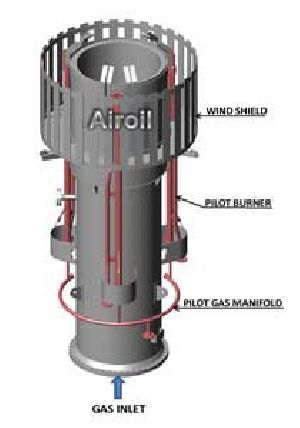
NON-SMOKELESS FLARES
The FN series flare tips are used where the environmental condition allows the burning of smoke producing gases. They are also used with gases which produce either no smoke or so little that smoke suppression with steam, air or high pressure gas is not required. Examples of gas used with these tips are Hydrogen, Blast Furnace waste gas, Coke Oven gas, Ammonia, Hydrogen Sulphide and Methane. ADVANTAGES Heat shield/wind shield supplied as alternatives Unique refractory lining system Good flame retention Energy efficient & reliable pilots Continuous Pilot monitoring by means of thermocouple mounted inside the pilot as standard. Optional UV/IR detection available. Rugged design gives Prolonged tip life MODE OF OPERATION The FN series flare tips are simple in design to allow straightforward flaring of gas not requiring specialized smoke suppression equipment. The FN series has been designed to operate with all available pilot and ignition system, e.g. Natural Draught, Natural Draught Splitter System and Forced Draught. FLAME STABILITY The FN series is supplied as standard with a slatted windshield to prevent flamelick and to help cool the top of the flare tip closest to the flame envelop. In order to prevent flame lift off from the tip, the FN series has unique flame retention lugs positioned at the tip exit of the flare tip. REFRACTORY SYSTEM The unique refractory lining system is secured to tip by heat resistant steel bull horn sprags. Many thousands of fine stainless steel needles are mixed thoroughly with the refractory to reinforce the material evenly over its full depth without producing expansion/contraction shear planes. This refractory installation procedure has been developed and proven over many years to give the longest possible operating life, even in the most arduous conditions.
...more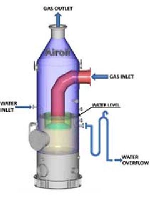
LIQUID SEAL DRUMS
The purpose of a liquid (commonly water) seal drums in a flare gas system in threefold:- PERFORMANCE FEATURES It operates as a non-return device preventing interaction from the outlet to the inlet of the drum. It operates as an upstream pressure relief valve preventing gas flow from the inlet to the outlet until a particular upstream pressure, frequently predetermined, is reached. It acts as a diversionary unit for :- Ground flare to elevated flare systems; ground flare to ground flare systems; Elevated flare to elevated flare systems; Fuel gas recovery systems to elevated flare. ADVANTAGES Designed to prevent pulsing of the gas flow to the flare. Ensures totally safe flare operation. Can be designed to accommodate a future fuel gas recovery scheme. Cost saving for fuel gas recovery installations. MODE OF OPERATION Part of the gas supply line dips below the surface of a reservoir of liquid contained in the drum. The depth to which this dip tube is covered by liquid controls the gas pressure required to cause flow. The pressure of the incoming gas displaces sustain the flow and maintains the liquid displacement. When the flow or pressure falls the liquid regains its original level and the flow ceases. Water is normally used as the sealing medium but other liquids may be used for low temperature applications or to prevent the gas being absorbed. DESIGN CHARACTERISTICS Many variations of seal drum are available to suit requirements but all serve the same basic function. In all cases the inlet tube forms the dip leg and the gas, having displaced all liquid from the tube, bubbles through the liquid to the riser. The level of liquid controls the back pressure. The basic concept is simple but if the liquid seal is not correctly designed, bubbling of gas through the liquid at low flows, or a surging motion of the liquid, can result in a pulsating flow of gas. A pulsating flow is a serious problem when the seal is used in conjunction with a smokeless flare tip. The smoke suppressing effect of the tip remains constant whilst the gas flow pulsates and this produces changes in the flame pattern creating smoke and excessive noise. An Airoil Flaregas designed liquid seal eliminates pulsating flows as well as ensuring that sufficient water is retained to seal the flare header as soon as flaring ceases. The liquid seal can be supplied as an integral part of a flare stack or as a remote unit. It is designed to pressure vessel codes as required, and can be horizontally or vertically positioned.
...more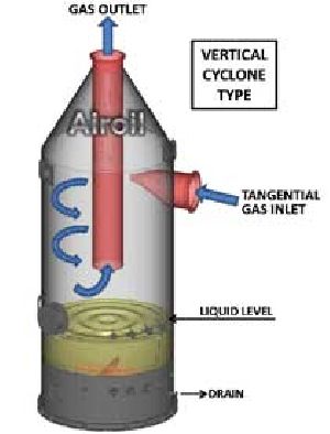
knock out drums
The Knock out drum is a vessel in the flare header designed to remove & accumulate condensed & entrained liquids from the relief gases. Both the horizontal & vertical design is a common consideration for the Knock out drum, which is determined based on the operating parameters as well as other plant conditions. If a large liquid storage capacity is desired and the vapour flow is high, a horizontal drum is often more economical. Also, the pressure drop across horizontal drums is generally the lowest of all the designs. Vertical knockout drums are typically used if the liquid load is low or limited plot space is available. They are well suited for incorporating into the base of the flare stack. DESIGN FEATURES Although horizontal and vertical knockout drums are available in many configurations, the differences are mainly in how the path of the vapour is directed. The various configurations include the following: Horizontal drum with the vapour entering one end of the vessel and exiting at the top of the opposite end (no internal baffling) Vertical drum with the vapour inlet nozzle entering the vessel radially and the outlet nozzle at the top of the vessel's vertical axis. The inlet stream should be baffled to direct the flow downward Vertical vessel with a tangential nozzle. Vertical centrifugal separators differ from vertical settling drums in that the flow enters tangentially and spins around a centre tube, which extends below the liquid inlet nozzle. The gas and liquid flow radially downward through the annulus causing liquid droplets to coalesce along the walls and collect in the bottom of the drum. The vapour changes direction once below the centre tube and flows upward to the outlet nozzle. To avoid liquid re-entrainment, vapour velocity has to be kept low in the turnaround section of the drum. An additional measure to prevent liquid re-entrainment is a baffle plate below the turnaround section of the drum. The maximum liquid level is the same as vertical settling drums Horizontal drum with the vapour entering at each end on the horizontal axis and a centre outlet Horizontal drum with the vapour entering in the centre and exiting at each end on the horizontal axis Combination of a vertical drum in the base of the flare stack and a horizontal drum upstream to remove the bulk of the liquid entrained in the vapour. This combination permits the use of larger values for the numerical constant in the velocity equation.
...more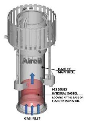
IGS INTEGRAL GASEELS
The Gaseel IGS Series, located integrally at the base of the flare tip, has been designed to prevent air ingress into the flare system and has a number of advantages over gas inversion seals. ADVANTAGES Lower purge gas rates on smaller diameter stacks Lower pressure drop Negligible structural load No maintenance Low capital cost MODE OF OPERATION The Gaseel functions by presenting a smaller cross sectional area of the stack to the rising gases, thereby reducing the volume of gas needed to maintain a fixed purge velocity. It also prevents the passage of air currents down the stack riser section. In order to give maximum protection to the stack, the Gaseel should be fitted inside the flare tip. Thus for a fixed flare tip length of 12 feet (which is common in the industry) and small diameter tip, the Gaseel is positioned a number of nominal diameters from the stack exit. The Gaseel operation consequently benefits not only from the reduction in cross-sectional area but also from positioning the control point relatively well down into the stack. At the other extreme, large diameter stacks do not benefit in the same way from the effect of fall off in oxygen percentage with depth of penetration and must rely solely on the reduction in cross-sectional area. Consequently the use of such a seal is seen to best advantage in small diameter stacks. DESIGN CHARACTERISTICS In order to minimize the amount of purge gas flow needed various seal device have been developed. One such device employs a double reversal of direction of flow (Flarex Seal) and has been used in the industry for many years. A simplified seal has also been developed by Airoil-Flaregas which is a conical device situated in the base of the flare tip itself. Normally when a stack is in shut down condition, unless special arrangements are made, the safest course is to assume that it is full of air. Subsequent introduction of a combustible gas means that at some stage, as the gas displace the air, a flammable mixture will result. In order to prevent an explosive condition developing it is possible, either to ensure that no ignition source is present during this period, or to replace the air with gas rapidly to preclude the danger of flame regression into the gas/air mixture. When the stack is filled with a gas which is lighter than air there is a natural tendency for this gas to decant, being replaced by air. A low of gas counteracts the decanting action and prevents air penetrating deeply into the stack. The depth of air penetration is a function of the gas velocity. By adopting a standard of acceptability for oxygen in the upper section of the flare it is possible to arrive at a range of purge gas flows which vary with flare diameter and depth of acceptable oxygen concentration in the stack.
...more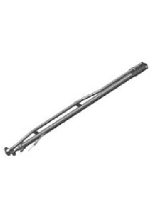
FLARE PILOTS
Airoil Flaregas flare pilots are suitable for use on all types of Elevated Flare Tips, Ground flares and Burn Pits, in the worst weather conditions which may exist off-shore or on-shore, from sub-zero ambient conditions of Antarctica to the sand/wind storms of Middle East and Africa. The pilots have very wide application ranging from standard LPG or natural gas to low BTU gases like bio gas or coke oven gas & also for gases with high hydrogen content. The pilot nozzle is basically a pilot stabilized tunnel burner designed for a high inspiration rate, normally 80% to 85% primary air. ADVANTAGES Energy efficient, stable & reliable performance. Reliable ignition in all weather condition Heat resisting nozzle casting Flame retention in all weather condition Thermocouple housing facility supplied Suitable for ignition of natural draught, forced draught, semi-forced draught, manual / automatic ignition systems. MODE OF OPERATION The Airoil Flaregas Flare Pilots are the inspiriting type of varying length, depending on the application. On elevated Flare Tips, the pilot is generally 2.7 meters long, whereas on Burn Pits the length could be 30 meters or more. The pilot nozzles have built-in flame retention and include a shield to ensure a stable flame and enable positive re-ignition in high winds. Ignition of the pilot is via a flame front generated at a remote panel and fed to the pilot nozzle via a 1 in. igniter tube. (The pilot gas is supplied via a ½ in. inlet to the venture with an air adjuster). The air is pre-mixed with gas in a 2 in. gas tube and is ignited at the nozzle by the flame front. FLAME INDICATION For flame indication, or flame failure, a heat resisting clad thermocouples is fitted internally in the nozzle and the gas mixture tube where it is protected from the main flame and cooled by the flow of gas passing over the thermocouple.
...more
AIR ASSISTED FLARES
The FAB series flare is used for smokeless combustion applications, where the use of steam is not desired. Smokeless combustion can be obtained even with heavy unsaturated hydrocarbon gases. ADVANTAGES Low operation costs. No steam required. 100% smokeless combustion Non-luminous, low noise combustion Low pressure air for smoke suppression Simple control system for normal/maximum operation Energy efficient & reliable pilots Continuous Pilot monitoring by means of thermocouple mounted inside the pilot as standard. Optional UV/IR detection available. MODE OF OPERATION There are two nodes of air supply; the first is a co-axial supply of air with the main gas riser centrally positioned. The second is an outside separate air riser alongside the main gas riser. The gas is distributed in the tip to a series of vanes with characterized slots for even gas spread into the air stream. The air is directed from the tip with a swirling action at high velocity and, with the even gas spread and turbulent air mixing at the tip outlet, efficient combustion is achieved. Secondary air is entrained by the turbulent discharge from the tip. The swirling action of the flame produces a well formed flame with low luminosity, unaffected by wind and producing minimum downward radiation. This is achieved by supplying up to 50% of stoichiometric air from the low pressure fan. PERFORMANCE FEATURES Full capacity can be flared smokelessly with only part of the combustion air supplied by a fan at low pressure. The fan can be staged so that efficient use of electrical power is achieved. The fan speed can also be automatically controlled. As a result, efficient combustion is achieved without the use of expensive steam and with minimum noise, producing a flame of low luminosity which does not disturb the environment. DESIGN CHARACTERISTICS The gas riser and air riser can be run separately or co-axially to the tip allowing flexibility in the mechanical design of the stack. The fan can be part of the stack structure, mounted separately at the base or remotely. The controls and ignition panel can be sited at the stack base or remotely as required. Airoil Flaregas low gas consumption pilots can be used with the choice of electric, non-electric, manual or automatic ignition systems. The use of forced draught air maintains the air and gas riser and the flare tip at low temperature and eliminates the need for a refractory lining. The extremely stable upright flame, achieved by using forced draught sir, minimizes ground level radiation and, therefore, lower stack can be used with safety. Furthermore, the short, well formed flame is less affected by cross winds and prevents flame lick. Liquid and/or gas seals can be accommodated into the flare system if required.
...more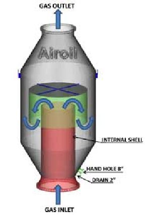
AFS MOLECULAR SEALS
The Molecular Seal AFS Series is located just below the flare tip and has been designed to prevent air ingress to the flare riser thus preventing the formation of an explosive mixture in the system. The seal is a gas inversion device causing the gas normally flowing in an upward direction to be turned through 180 degree in the original direction of the flow. In a static condition, gases lighter then air will tend to collect in the upper bend sealing off the stack against the back flow of air. Heavier gases will tend to settle in the lower bend with the same effect. Some wind and atmospheric action will affect these interfaces slightly, and molecular diffusion of the two gases will take place at the interface. In order to counteract these effects a small continuous bleed of gas, dependant on the flare nominal diameter, must be maintained in order to ensure that air does not penetrate the seal. ADVANTAGES Molecular Seals have a safety factor for momentary loss of purge gas Lower purge gas rates Cost saving on purge gas No maintenance required Robust construction Molecular Seals can be used as a support for a flare tip lifting davit DESIGN CHARACTERISTICS Flare stacks are designed to dispose of flammable gases safely by ensuring the combustion of these gases at the exit of the stack (flare tip). It is undesirable to have a flarestack filled with a mixture of gas and air (oxygen) within the flammable limits because of the dangers of internal flash-back or explosion. Normally when a stack is in a shut down condition, unless special arrangements are made, the safest course is to assume that it is full of air. Subsequent introduction of a combustible gas means that at some stage, as the gas displaces the air, a flammable mixture will result. In order to prevent a dangerous situation arising, it is possible either to ensure that no ignition source is present during this period, or to replace the air with gas rapidly to preclude the danger of flame regression into the mixture. The most common and most acceptable safety measure is to purge the system with a non-flammable gas prior to introducing the combustible gas, thus injecting a barrier between the two active agents. If the period between starting the purge and introducing flammable gas is to be prolonged a reasonable course of action is to include in the system a device which assists in keeping air from the stack, whilst reducing the amount of purge gas needed to accomplish this. The use of such a device is also advantageous when it is necessary to keep a flare on stand-by but not operating for a long period, when saving in purge gas will pay for the capital outlay on the device.
...more
Polymers
Be first to Rate
Rate ThisOpening Hours
Share your Correspondence Details to receive messages from Airoil Flaregas Pvt. Ltd.